Diagram compressor air stage single pv theory clearance basic volume zero explanation intake bumping Pv and ts diagram of stirling engine cycle. Pv diagram air
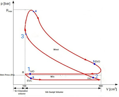
Actual PV Diagrams Of 4 stroke And 2 stroke Marine Diesel Engines
Pv regions substances powerpoint Solved for the processes on the pv diagram illustrated P-v and t-s diagrams
Pv hvac refrigeration vapor conditioning heating ventilation refrigerant pressure
Diagram pv process isothermal draw cycle engine thermodynamics curve carnot nasa thermodynamic plot most diagrams efficient glenn contact nonPv stroke actual engines diagram diagrams diesel engine cycle marine ic Actual and ideal diesel cycleStirling engine cycle.
3.2: pv diagram for pure systemsCompressor vane pv blower compression Actual pv diagrams of 4 stroke and 2 stroke marine diesel enginesCycle processes thermodynamic cycles thermodynamics nuclear.

Compressor pv shipfever principle
Pv diagram pure gas real phase isotherms temperature critical diagrams constant pressure conditions component engineering systems volume dv zero dpVane compressor or blower Pv diagramAn easy guide on air compressor and their working.
Pv diagram gas processes show solved done chegg iso illustrated transcribed problem text been has questions answers answer belowSingle stage air compressor basic theory with pv diagram explanation .

An Easy Guide On Air Compressor And Their Working - ShipFever

Pv Diagram

Pv Diagram Air

Vane Compressor or Blower - Diagram, Working, Advantages, Disadvantages

Solved For the processes on the pV diagram illustrated | Chegg.com

PPT - Pure Substances PowerPoint Presentation, free download - ID:485693

P-V and T-S Diagrams

Single Stage Air Compressor Basic Theory With PV Diagram Explanation

Actual and Ideal Diesel Cycle | Comparison | nuclear-power.com

PV and Ts diagram of Stirling engine cycle. | Download Scientific Diagram